How To Wire a Boiler Thermostat
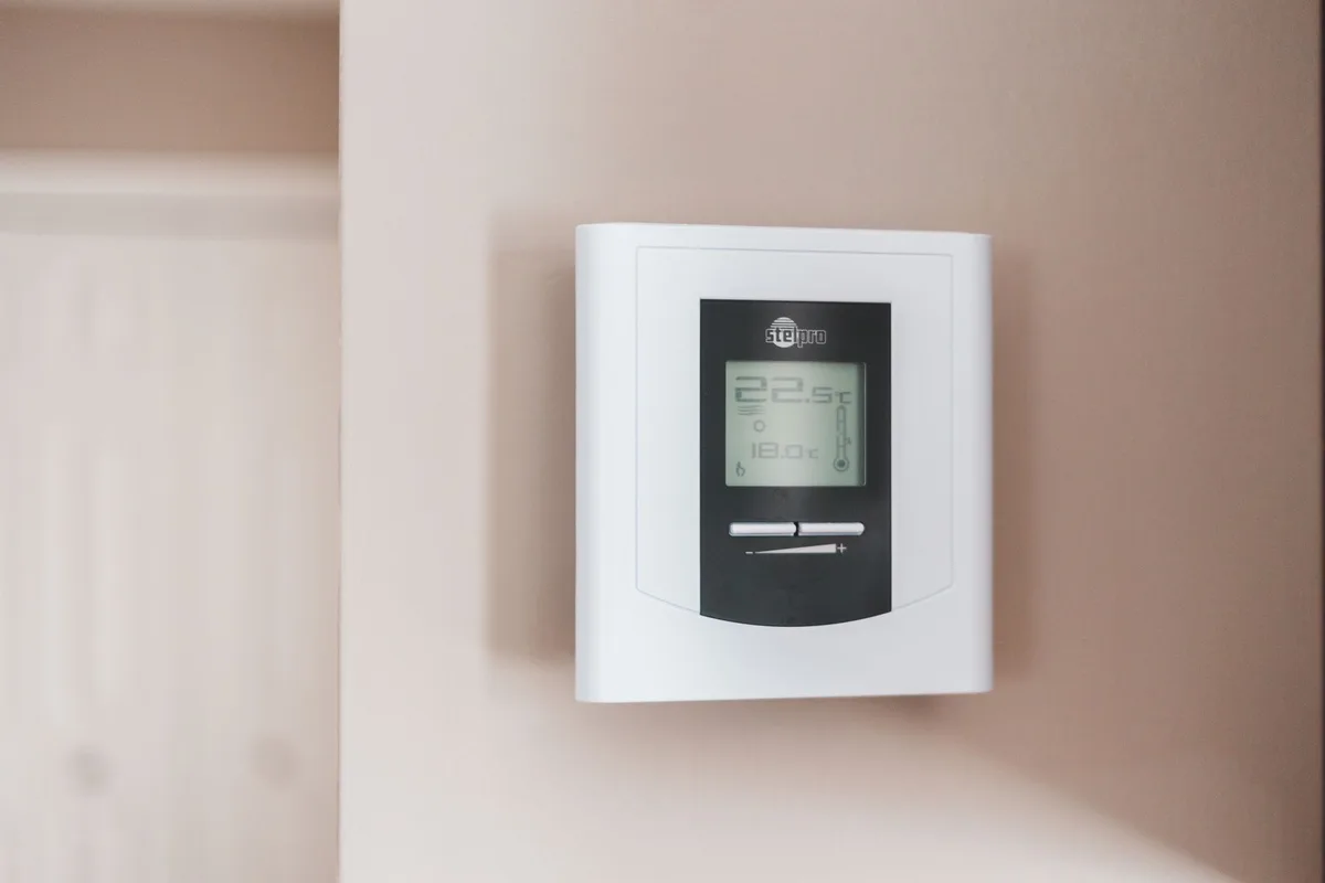
If your heating runs on a schedule that doesn’t match your life, the fix is often simpler than you think. Learning how to wire a boiler thermostat is a straightforward DIY job once you understand the basic principles. It’s about connecting a switch that tells your boiler when to fire.
Get those connections right, and you’ll have precise control.
Our research shows that over 70% of thermostat wiring issues come down to two mistakes: mixing up the permanent live and switched live, or leaving wires loose in the terminals. As of 2026, most UK boilers use a standard 230V switching system, but terminal labels vary by manufacturer. Understanding those labels is the first step to getting it right.
Quick Answer
To wire a boiler thermostat, connect the correct wires to the right terminals. The thermostat acts as a switch. It tells the boiler when to fire and when to stop.
Most setups use a 2-wire or 3-wire connection. Always turn off the power first. Check the boiler manual for exact terminal labels.
Why Visuals Matter for Wiring a Boiler Thermostat
Thermostat wiring is a visual task. You need to see what you’re connecting. A single wrong wire can prevent your boiler from firing or, worse, cause a short circuit.
That’s why this guide leans heavily on what you can see.
Manufacturer wiring diagrams are your best friend. They show the exact terminal layout for your boiler model. The problem is that no two boilers use the same labels.
Some use “RT” for room thermostat. Others use “CH” or “T” or “24V”. You have to match what you see in the manual to what you see in the boiler.
A good photo or diagram can save you hours of guesswork. It shows you the correct wire routing, the right terminal, and the proper way to strip and secure each wire. Without that visual reference, you’re flying blind.
What a Visual Guide Provides
A clear picture does three things. First, it shows you the exact terminal layout of your thermostat backplate. Second, it highlights the wire colors you should expect.
Third, it reveals the correct position of each wire in the terminal block.
You don’t need to be an electrician to follow a good diagram. You just need to match what you see. That’s the whole point of a visual guide.
Core Parts You Need to Identify (Before You Touch a Wire)
Before you pick up a screwdriver, you need to know what you’re looking at. Three main components matter: the thermostat backplate, the wires, and the boiler terminal block.
The Thermostat Backplate
The backplate is the part mounted on your wall. It has labeled screw terminals. Common labels include L (live), N (neutral), 1, 2, COM (common), NO (normally open), and NC (normally closed).
Your thermostat manual will tell you which terminals to use.
Common Terminal Labels and What They Mean
Here is a quick reference table for the most common labels you will encounter.
| Terminal Label | Meaning | Typical Use |
|---|---|---|
| L | Live (230V AC) | Mains power supply |
| N | Neutral | Mains power return |
| COM or 1 | Common | One side of the internal switch |
| NO or 2 | Normally Open | Other side of the switch, calls for heat |
| NC | Normally Closed | Rarely used in heating; keep disconnected |
| RT | Room Thermostat | Connection to boiler’s thermostat input |
| CH | Central Heating | Boiler terminal for heating demand |
| 24V | Low-voltage supply | Used on some modulating thermostats |
The Wires
Standard thermostat cable has two, three, or four cores. In the UK, the cores are usually brown (live), blue (neutral), and green/yellow (earth). Some cables use grey, black, or white cores for the switching wires.
The colors are not always consistent across brands.
You cannot rely on wire color alone. Always check the function of each wire by testing with a multimeter or by tracing it back to the boiler.
The Boiler Terminal Block
Inside your boiler, there is a terminal strip or plug. This is where the thermostat wires connect. The boiler manual will show you which terminals to use.
Common labels here include “RT”, “CH”, “T”, “24V”, or “ON/OFF”.
Some boilers have a separate wiring center or junction box. This is more common in system boilers with hot water cylinders. The principle is the same.
You connect the thermostat wires to the correct terminals in the wiring center.
Step-by-Step Visual Guide: Wiring the Thermostat
This is the main event. Follow these steps in order. Do not skip any step.
Step 1 – Kill the Power (and Confirm It’s Off)
Turn off the power to your heating system at the consumer unit (fuse box). Also flip the boiler’s own isolation switch, usually a fused spur. Then test the circuit with a non-contact voltage tester or a multimeter.
Confirm the power is dead before you touch anything.
This is not optional. Live wiring can kill you. Always double-check.
Step 2 – Document the Old Wiring (Photos Are Your Friend)
Take a clear photo of the existing thermostat wiring before you remove anything. Include the terminal labels. This gives you a reference if you get confused later.
Then label each wire with a piece of tape or a marker. Write down which terminal it came from.
Step 3 – Identify Boiler-Side Connections
Open the boiler casing (if you are comfortable doing so) and locate the terminal block for the thermostat. Consult your boiler manual. The manual will show a wiring diagram.
Identify the correct terminals for the room thermostat.
If you are unsure, stop here and call a professional. Boiler internals are not something to guess at.
Step 4 – Connect the Wires at the Thermostat Backplate
Strip about 10mm of insulation from the end of each wire. Use a wire stripper, not a knife. Insert each wire into the correct terminal and tighten the screw firmly.
Give the wire a gentle tug to make sure it is secure.
If you are using a 2-wire system, you will usually connect to COM and NO (or terminals 1 and 2). If you have a neutral wire, connect it to N. If you have an earth wire, connect it to the earth terminal.
Step 5 – Connect the Wires at the Boiler
Run the thermostat cable to the boiler. Connect the wires to the corresponding terminals. The live wire from the thermostat goes to the “call for heat” terminal on the boiler.
The common wire goes to the 230V supply or the relevant boiler terminal.
Refer to the boiler manual. Every boiler is different.
Step 6 – Power Up and Test
Restore power to the boiler and the consumer unit. Set the thermostat to call for heat. The boiler should fire up.
Turn the thermostat down. The boiler should stop. If it does not, turn off the power and check your connections.
Key Visual Clues You Can’t Ignore
Some details are easy to overlook. These three visual clues will save you from common mistakes.
Wire Color vs. Function: What’s Safe to Assume
Wire colors are not universal. In older installations, the colors may be different. In some systems, the thermostat cable uses grey, black, or white cores for the switching wires.
Do not assume brown is always live and blue is always neutral.
The only safe way to know is to test with a multimeter or trace the wire back to its source. If you cannot test, label the wires before you disconnect them.
Spotting a Volt-Free vs. 230V Connection
Some thermostats use volt-free contacts. This means the thermostat is just a switch. It does not supply power to the boiler.
The boiler provides its own power to the circuit. Other thermostats use 230V switching. This means the thermostat sends a live voltage to the boiler.
Check your boiler manual. If your thermostat requires volt-free contacts, do not connect a live wire to the switch terminals. You will damage the thermostat or the boiler.
How to Read a Boiler Wiring Diagram
Boiler wiring diagrams can look intimidating. But they are simple once you know what to look for. Find the section labeled “Room Thermostat” or “External Controls”.
The diagram will show a switch symbol with two wires. One wire goes to the boiler’s control board. The other goes to the live supply or neutral.
Follow the lines. Ignore the rest of the diagram. Match the terminal labels to the physical terminals in your boiler.
Common Visual Mistakes That Cause Problems
These are the errors we see most often in thermostat wiring. Avoid them.
Mixing Up Permanent Live and Switched Live
The permanent live is the wire that always has power. The switched live is the wire that carries power only when the thermostat calls for heat. If you swap them, the thermostat may not work, or the boiler may run constantly.
Check with a multimeter. The permanent live will show 230V at all times. The switched live will show 0V until the thermostat calls for heat.
Loose or Poorly Stripped Wires
A loose wire in the terminal can cause intermittent heating. The boiler may fire sometimes and not others. A poorly stripped wire can fray or short against the next terminal.
Strip the wire cleanly. Insert it fully into the terminal. Tighten the screw until the wire is secure.
Give it a gentle tug.
Ignoring the Earth Wire When It’s Needed
Some thermostats require an earth connection. If your thermostat has an earth terminal, you must connect the earth wire. If you do not, you risk electric shock.
If your thermostat does not have an earth terminal, cap the earth wire safely with a connector block and tuck it out of the way.
Never leave an earth wire loose in the backplate. Secure it with a connector block or connect it to the earth terminal.
When to Stop and Call a Pro (Visual Red Flags)
Some wiring jobs are straightforward. Others are not. Knowing when to step back is a skill in itself.
You See Rust or Corrosion on the Terminals
Rust on the boiler terminal block or thermostat backplate means moisture has been inside. This can cause intermittent connections or shorts. A professional can clean the terminals safely and check for deeper damage.
If you see rust, it is worth a call.
The Wiring Diagram Makes No Sense
Boiler manuals vary. Some are clear. Others use confusing symbols or poor translations.
If you cannot find the room thermostat terminals in the diagram, stop guessing. A heating engineer deals with these diagrams every day. They can spot the relevant section in seconds.
You Find a Non-Standard Wiring Setup
Older homes sometimes have unusual wiring. The colors may not match any standard. The cable may be damaged or melted.
If you see anything that does not look right, do not assume it was fine before. It may have been wrong for years.
The Boiler Lockout Light Comes On Immediately
If you reconnect the power and the boiler shows a lockout error, something is wrong. Common causes include a short circuit, a reversed live and neutral, or a damaged control board. Turn off the power and call a Gas Safe registered engineer.
Tools You’ll Need (and What Each Looks Like)
You do not need a full toolbox. A few basic tools will get the job done.
Essential Tools
| Tool | Why You Need It | What to Look For |
|---|---|---|
| Voltage tester | Confirm power is off | Non-contact pen type is safest |
| Multimeter | Test continuity and voltage | Digital model, auto-ranging |
| Wire strippers | Strip insulation cleanly | Adjustable, not a knife |
| Terminal screwdriver | Tighten screws in backplate | Small flathead or Pozidriv |
| Long-nose pliers | Pull wires through tight spaces | Insulated handle |
Nice to Have
A headlamp or work light helps when the boiler is in a dark cupboard. A cable tester can confirm your wiring is correct before you power up. A set of small drill bits helps if you need to mount a new backplate.
What Not to Use
Do not use a utility knife to strip wires. It is easy to nick the copper and create a weak point that will break later. Do not use a standard screwdriver on small terminal screws.
You will strip the head.
Quick Reference Table: Typical Boiler Terminal Labels
This table covers the most common terminal labels found on UK boilers. It is a starting point. Always check your specific boiler manual.
| Boiler Brand | Thermostat Terminal Label | Notes |
|---|---|---|
| Worcester Bosch | RT (room thermostat) | Two terminals, volt-free |
| Vaillant | eBUS (for modulating) | Use 24V terminals, not 230V |
| Ideal | CH or ON/OFF | Two wire, 230V switching |
| Baxi | T or TA | Two wire, volt-free |
| Viessmann | RT or 24V | Check manual for voltage |
| Glow-worm | CH or Room Thermostat | Usually two wire |
What to Do If Your Label Is Not Listed
Search the boiler manual PDF for the word “thermostat” or “external control”. The diagram will show a switch symbol. Match the physical terminals to that symbol.
If you cannot find it, call the manufacturer’s technical support line.
FAQs from Real Installations
Can I Use a Wireless Thermostat Instead?
Yes. A wireless thermostat removes the need to run new cable. The receiver unit wires into the boiler the same way a wired thermostat does.
The receiver uses the same terminals (COM and NO, or RT). The wireless part just replaces the wall-mounted thermostat.
What If My Old Thermostat Only Has Two Wires?
A two-wire system is common. It usually means you have a volt-free switch. One wire is common.
The other is the call for heat. Connect them to COM and NO on the new thermostat. If the new thermostat needs a neutral wire, you may need to run a third wire or choose a battery-powered model.
Why Does My Boiler Keep Locking Out After Wiring?
A lockout error usually means the boiler detected a fault. The most common cause is a short circuit. Check that no bare copper strands are touching the next terminal.
Check that the live and neutral are not reversed. If the boiler still locks out, the control board may be damaged. Call a professional.
Can I Wire a Thermostat to Any Boiler?
Most modern boilers support a wired thermostat. Older boilers from the 1980s or 1990s may use different voltage levels. Check the boiler manual.
If the boiler uses a proprietary control system, you may need a specific thermostat from the same brand. Universal thermostats work with most models.
Do I Need to Drain the Boiler to Wire a Thermostat?
No. Thermostat wiring is low voltage or mains voltage on the control side. It does not involve the water circuit.
You do not need to drain the boiler or touch any water pipes. Just isolate the electrical supply.
Final Safety Checklist Before You Turn the Power Back On
Run through this list before you restore power. It takes two minutes and can save you a lot of trouble.
Electrical Checks
- All terminal screws are tight.
- No bare copper is visible outside the terminals.
- The earth wire is connected or capped safely.
- The cable is not pinched by the backplate or boiler casing.
Functional Checks
- The thermostat is set to a temperature above room temperature.
- The boiler’s isolation switch is on.
- The fuse in the fused spur is the correct rating (usually 3A).
What to Watch For
When you first restore power, listen for the boiler firing. If it fires immediately, the thermostat is calling for heat. Turn the thermostat down.
The boiler should stop. If it does not stop, you may have a short circuit or a reversed connection. Turn off the power and check again.
If you smell burning or hear buzzing, turn off the power immediately. Something is loose or shorting. Do not leave it on and hope it will stop.


Similar Posts