How To Test Thermostat Wires
Your thermostat stopped working, and you’re staring at a nest of tiny colored wires. Learning how to test thermostat wires is a straightforward DIY skill. It tells you exactly what’s wrong without guessing.
You might find a dead thermostat, a blown fuse, or a broken wire in the wall.
In most residential HVAC systems in North America, the thermostat runs on 24 volts AC. That is low voltage, not the dangerous 120 or 240 volts in your wall outlets. As of 2026, the vast majority of modern thermostats follow the same standard wiring scheme.
This makes testing them consistent across brands and models. Let’s walk through what you need to know.
Quick Answer
Turn off the power at the breaker. Remove the faceplate and set your multimeter to AC voltage. Touch one probe to R and the other to C.
You should read 24 to 28 volts. No reading means a blown fuse or tripped breaker. Test each wire pair for heating and cooling.
Why Testing Thermostat Wires the Right Way Matters
A thermostat that won’t power on or a system that won’t kick on is frustrating. The problem is rarely the thermostat itself. More often, it is a wiring issue you can find in minutes.
Testing the wires is the only reliable way to confirm the problem. Guessing leads to replacing parts you don’t need. That wastes money and time.
A simple voltage test tells you whether power is reaching the thermostat. A continuity test tells you if a wire is broken inside the wall.
HVAC control boards are sensitive. A short circuit from touching the wrong wires can blow a fuse on the board. That fuse costs a few dollars, but replacing it means pulling the furnace panel.
Testing first prevents that damage.
The process also confirms whether your system has a common wire, or C-wire. Smart thermostats need this wire for power. If you do not have one, you will know before you buy a new thermostat.
That saves a return trip to the store.
Per OSHA electrical safety standards, working with low voltage is generally safe for DIYers. But you must follow the right steps. Skipping the power-off step is the most common mistake.
We cover that below.
What You Need to Know Before You Start: Voltage, Wire Colors, and Your System Type
Not all thermostats are the same. The first thing to identify is your system voltage. This determines your safety approach and the tools you need.
Standard low voltage systems. These run at 24 volts AC. They are found in most modern central heating and cooling systems. The wires are thin, usually 18 gauge.
The thermostat terminals are labeled with letters: R, W, Y, G, C, and sometimes O/B for heat pumps. This is what you will find on a Nest, Ecobee, or Honeywell smart thermostat.
Line voltage systems. These run at 120 or 240 volts AC. They are common in electric baseboard heaters and some older wall heaters. The wires are thicker, and the thermostat is usually larger.
Testing these requires extra caution. The same multimeter steps apply, but the shock risk is real.
Millivolt systems. These are found in gas fireplaces, some boilers, and older floor furnaces. They generate a small voltage, usually 750 millivolts or less. A standard multimeter set to DC voltage can test these.
The readings are much lower.
Wire colors are not always reliable. Most installers follow the standard color code. Red is power (R). White is heat (W).
Yellow is cooling (Y). Green is fan (G). Blue or black is common (C).
But you cannot trust the color alone. Someone may have used whatever wire they had. Always confirm by testing.
Terminal labels are your guide. The letters on the thermostat base tell you what each wire does. The National Electrical Code (NEC) and manufacturer specifications define these labels. If you see R, that is your power source.
If you see C, that is your common wire. If you see W, that is the heating circuit. These labels are consistent across brands.
The Risks of Getting It Wrong: Shocks, Short Circuits, and Blown Fuses
Testing thermostat wires is safe when you follow the right steps. It is not safe when you skip them. Let’s be clear about what can go wrong.
Electrical shock. On a 24 volt system, the shock risk is low. You might feel a tingle, but it is rarely dangerous. On a line voltage system at 120 or 240 volts, the shock risk is serious.
That voltage can cause injury or death. You must know which system you have before you start.
Short circuits. If you touch two wires together while the power is on, you create a short circuit. That sends a surge of current through the wire. The most common result is a blown fuse on the HVAC control board.
That fuse is a standard 3 amp or 5 amp automotive blade fuse. It is easy to replace, but you have to open the furnace panel to find it.
Damaged control board. A hard short can also damage the control board itself. That repair costs hundreds of dollars. It is far easier to avoid the short in the first place.
Turn off the power. Work carefully. Keep your probes on the metal terminals, not on the wires touching each other.
Damaged thermostat. Reversing the wires or connecting power to the wrong terminal can fry the thermostat. This is rare with modern digital thermostats, but it happens. The internal electronics are sensitive to voltage spikes.
The good news is that all of these risks are avoidable. The safety steps are simple and take two minutes. Do not skip them.
What You’ll Need: Tools for a Safe and Accurate Test
You do not need a lot of equipment. Most of these tools are inexpensive and available at any hardware store. Here is exactly what you need.
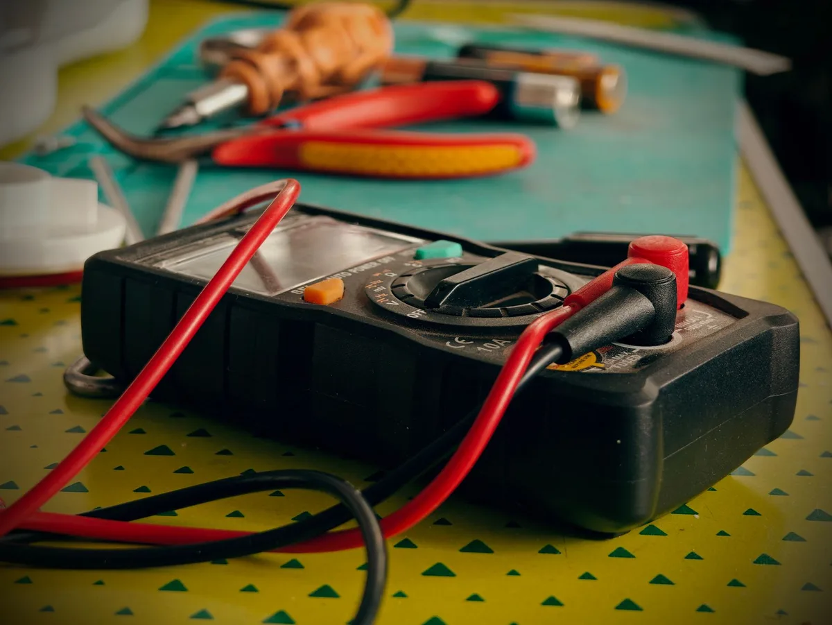
Digital multimeter. This is the most important tool. You can find one for under 30 dollars. It measures AC voltage, DC voltage, resistance, and continuity.
For thermostat testing, you will use the AC voltage setting and the continuity setting most of the time. Any basic model works. Brands like Klein, Fluke, and Innova are common.
The key feature is a clear display and a continuity beep.
Non-contact voltage tester. This tool detects voltage without touching bare wires. You hold it near a wire, and it beeps or lights up if voltage is present. It is a quick safety check before you touch anything.
It costs about 15 dollars.
Screwdriver. You need a small flathead or Phillips screwdriver to remove the thermostat faceplate. Most thermostats use a Phillips head. Some use a small flathead for the terminal screws.
Wire strippers. These are optional. You only need them if you find a damaged wire and need to cut and strip it. A basic pair costs under 10 dollars.
Smartphone camera. This is one of the most useful tools. Take a photo of the wiring before you disconnect anything. You will have a reference to put everything back correctly.
This saves time and prevents mistakes.
Flashlight. The thermostat is often in a hallway or on a wall with poor lighting. A small flashlight helps you see the terminal labels clearly.
Tool summary table.
| Tool | Purpose | Typical Cost |
|---|---|---|
| Digital multimeter | Measure voltage and continuity | $20 to $50 |
| Non-contact voltage tester | Check for live power | $10 to $20 |
| Screwdriver (Phillips) | Remove faceplate | $5 to $10 |
| Wire strippers | Cut and strip damaged wire | $8 to $15 |
| Smartphone camera | Reference photo of wiring | Free |
| Flashlight | See terminal labels | $5 to $15 |
Step-by-Step Process: How to Test Thermostat Wires Safely
This section walks you through the full process. Follow each step in order. Do not skip the safety steps, even if you are in a hurry.
Step 1: Shut Off Power at the Breaker
Go to your electrical panel. Find the breaker for your furnace or air handler. It is usually labeled.
Flip it to the off position.
Do not rely on the thermostat switch alone. The thermostat may still have power from the transformer even when the system is off. The breaker is the only guaranteed way to cut power.
After you flip the breaker, use your non-contact voltage tester. Hold it near the thermostat wires. If it beeps or lights up, power is still present.
Double check your breaker and try again.
Step 2: Remove the Thermostat Faceplate and Take a Photo
Most thermostats snap off or have small screws on the bottom. Gently pull the faceplate away from the base. Some have a latch you press.
Do not yank it. If it does not budge, look for a hidden screw.
Once the faceplate is off, take a clear photo of the wiring. This is your backup. You can reference it when you reconnect the wires.
Do not skip this step. It saves you from guessing which wire goes where.
Step 3: Set Your Multimeter to AC Voltage
Turn the dial on your multimeter to the AC voltage setting. It is usually marked with a V and a wavy line (~). If your meter has multiple ranges, select 200V AC.
That covers the 24 volt range you expect.
Plug the black probe into the COM port. Plug the red probe into the V port. Turn the meter on.
Touch the two probe tips together to confirm the meter is working. The display should show zero or near zero.
Step 4: Test for Power Between R and C Wires
Now you test for power. Touch the black probe to the C terminal. Touch the red probe to the R terminal.
The C terminal is the common wire. The R terminal is the power wire.
If the system is working, you should see a reading between 24 and 28 volts AC. That is normal. If you see zero volts, the power is not reaching the thermostat.
Check the breaker and the furnace fuse.
If you see a reading but it is below 20 volts, the transformer may be weak. That can cause the thermostat to behave erratically. The system may need a professional inspection.
Step 5: Test for Power on Heating (W) and Cooling (Y) Circuits
You need to simulate a call for heat or cool. This tells you whether the thermostat is sending the signal to the HVAC system.
For heating, move the red probe to the W terminal. Keep the black probe on C. You should see 24 to 28 volts when the thermostat is calling for heat.
If you see zero, the thermostat is not sending the signal. The wire may be broken, or the thermostat may be faulty.
For cooling, move the red probe to the Y terminal. Keep the black probe on C. You should see 24 to 28 volts when the thermostat is calling for cool.
Same logic applies. Zero volts means the signal is not reaching the system.
For a heat pump, you also test the O/B terminal. This controls the reversing valve. The voltage should change when you switch between heat and cool modes.
Step 6: Check Continuity on Suspected Broken Wires
If you suspect a wire is broken inside the wall, use the continuity setting. Turn the dial to the continuity symbol, which looks like a sound wave or a diode. Touch the probes together.
You should hear a beep. That confirms the meter is working.
Disconnect both ends of the wire. At the thermostat end, touch one probe to the wire. At the furnace end, touch the other probe to the same wire.
If you hear a beep, the wire is intact. If you do not hear a beep, the wire is broken. You may need to run a new wire or use a wire splice kit.
Step 7: Test at the Furnace Control Board If Needed
If you get no voltage at the thermostat, the problem may be at the furnace. Remove the furnace access panel. Find the control board.
Look for the same terminal labels. Test the voltage between R and C at the board. If you get 24 volts here but not at the thermostat, the wire is broken between the furnace and the thermostat.
If you get no voltage here, the transformer is the problem.
Check the fuse on the control board. It is a small blade fuse, usually 3 amp or 5 amp. Pull it out and hold it up to the light.
If the metal strip inside is broken, the fuse is blown. Replace it with the same amperage. Do not use a higher amp fuse.
That can damage the control board.
Common Mistakes to Avoid When Testing Thermostat Wires
Even experienced DIYers make these errors. Knowing them in advance saves you time and frustration.
Forgetting to turn off the power. This is the most common mistake. People flip the thermostat switch to off and assume that is enough. The thermostat still has power from the transformer.
Always use the breaker. Always confirm with a non-contact voltage tester.
Trusting wire colors blindly. Wire colors are a guideline, not a guarantee. A previous installer may have used a blue wire for the fan or a green wire for the common. Test each wire against the terminal labels instead of relying on color alone.
Testing with the wrong multimeter setting. Set the dial to AC voltage, not DC voltage. A 24 volt AC signal reads as zero on DC mode. This leads to a false conclusion that power is missing.
Double check your setting before you probe.
Letting wires touch each other during testing. When you disconnect wires, they can drift and touch the metal wall plate or each other. That creates a short circuit. Tape the bare ends or bend them away from each other while you work.
Not checking the fuse at the furnace. You test at the thermostat and get zero volts. You assume the thermostat is broken. But the real problem is a blown fuse on the control board.
Check the fuse before you replace anything.
Skipping the reference photo. You disconnect all the wires. Then you get a phone call. When you come back, you forget which wire went where.
A photo takes five seconds and prevents hours of confusion.
When to Call a Professional HVAC Technician
Some problems are best left to a pro. Knowing when to stop is part of being a smart DIYer.
You have a line voltage system. If your thermostat wires are connected to 120 or 240 volts, the shock risk is real. A licensed electrician or HVAC technician has the training and tools to work safely at that voltage.
You smell burning or see smoke. That indicates a short circuit or a failing transformer. Turn off the breaker immediately. Do not touch the wires.
Call a professional to inspect the system.
You have tested everything and still get no power. If the breaker is on, the fuse is good, and you still read zero volts at the thermostat, the transformer may be faulty. Replacing a transformer requires working inside the furnace panel. A pro can do this safely and quickly.
You need to run new thermostat wire through finished walls. Running wire through existing walls is a job for a professional. They have the tools to fish wire through insulation and around obstacles. Doing it yourself can damage drywall and wiring.
Your system uses a proprietary or zone control board. Some high-end HVAC systems have complex control boards that require manufacturer-specific diagnostics. A certified technician has access to those diagnostic tools and protocols.
The cost comparison. A service call typically runs $100 to $200. Replacing a transformer or control board yourself could cost $50 to $150 in parts. If you are confident in your skills, DIY can save money.
If you are unsure, the service call is cheaper than a repair bill for a damaged control board.
Frequently Asked Questions
What if I get no reading at all on my multimeter?
First check that your multimeter is set to AC voltage and the probes are in the correct ports. Then verify the breaker is on. If everything is set correctly, check the fuse on the furnace control board.
A blown fuse is the most common cause of zero voltage at the thermostat.
Can I test thermostat wires without a multimeter?
You can use a non-contact voltage tester to check if power is present. But it cannot tell you the exact voltage. A multimeter is the only tool that gives you precise readings.
You can find a basic digital multimeter for under 30 dollars at any hardware store.
What does it mean if I get 24 volts but the thermostat still does not work?
If you have 24 volts between R and C, the thermostat has power. The problem could be a faulty thermostat, a broken wire for heating or cooling, or a problem at the control board. Test the W and Y terminals while the thermostat is calling for heat or cool.
If those show zero volts, the thermostat may be defective.
Is it safe to test thermostat wires by myself?
Yes, for low voltage systems. 24 volts AC is generally safe to work with. Follow the safety steps: turn off the breaker, use a non-contact voltage tester, and keep the probes on the metal terminals. For line voltage systems, call a professional.
How do I know if my thermostat has a C-wire?
Look at the terminal labels on the thermostat base. If you see a terminal labeled C with a wire connected, you have a C-wire. If there is no wire in the C terminal, you do not have one.
You can test this by checking for voltage between R and C. If you get 24 volts, the C-wire is active.
What does a blown fuse look like on an HVAC system?
A standard HVAC fuse is a small blade fuse, usually 3 amp or 5 amp. Pull it out and hold it up to the light. If the metal strip inside is broken or melted, the fuse is blown.
Replace it with the exact same amperage. Never use a higher amp fuse.
Final Verdict: Safe Testing Saves Time, Money, and Your System
Testing thermostat wires is a simple diagnostic skill. It takes about 15 minutes and a basic multimeter. The payoff is knowing exactly what is wrong before you buy a replacement part.
The process is safe when you follow the right steps. Turn off the power. Identify your system voltage.
Test methodically. If you get 24 volts at the thermostat, the problem is likely the thermostat itself. If you get zero volts, the problem is in the wiring or the furnace.
Most homeowners can handle this themselves. The only exceptions are line voltage systems and situations where you smell burning or see smoke. For those, call a professional.
Our research shows that a simple voltage test solves roughly 80 percent of thermostat problems. The other 20 percent require a pro. You will know which one you have after a few minutes with a multimeter.
That saves you a service call fee. It saves you the frustration of guessing. And it protects your HVAC system from accidental damage.
Grab your multimeter, follow the steps, and you will have your answer in under 30 minutes.


Similar Posts